


Carbon Fiber Solutions for Aerospace Structural Components
- 2026-09-16
Build an aerospace structure once and you live with it for twenty years. That is the quiet rule behind every material decision on an aircraft or spacecraft programme, and it is the reason carbon fiber reinforced polymer (CFRP) moved from experimental skins in the 1980s to primary load-bearing parts today. This solution guide is written for the engineers and procurement teams who are not asking whether carbon fiber belongs on an aerospace structure, but which forms to buy, where each one goes, and what has to be right for the part to pass qualification and survive certification.
Below we walk through the weight problem as the industry actually experiences it, map the major airframe and spacecraft sub-assemblies to specific carbon fiber product forms, give the measured reasons behind each benefit, and finish with the selection and processing rules that keep a programme out of trouble. If you are sourcing aerospace-grade composites, the last section explains what Tanchain can supply and how to specify it.
What this guide covers
The Aerospace Weight Problem, Stated Precisely
The structural mass fraction constraint
Fuel burn, range, and payload coupling
Why metal substitution alone runs out of road
Where Carbon Fiber Goes: Airframe Sub-Assembly Map
Primary structure: wing skins, spars, stringers, and frames
Secondary structure: fairings, panels, and interior support
Control surfaces: ailerons, elevators, rudders, and actuators
Engine and nacelle components
Spacecraft bus, satellites, and launch vehicle structure
The Product Forms, One by One
3.1 Carbon fiber filament and tow
3.2 Carbon fiber fabric and multiaxial NCF
3.3 Carbon fiber prepreg
3.4 Carbon fiber plates and laminates
3.5 Pultruded and roll-wrapped carbon fiber tubes and profiles
The Measured Case: Why CFRP Wins in Aerospace
4.1 Specific strength and specific stiffness
4.2 Fatigue behaviour: slow, predictable, inspectable
4.3 Thermal expansion matching for precision structures
4.4 Dimensional stability and moisture effects
4.5 Corrosion and galvanic behaviour
Selection Matrix: Requirement to Product Form
Processing and Qualification Notes
6.1 Lay-up orientation is the design, not a detail
6.2 Curing route decides your void content
6.3 Machining, drilling, and fastener practice
6.4 Galvanic isolation and lightning strike protection
6.5 Inspection and traceability
Supporting Fibers: Aramid and Pre-Oxidized in the Same Programme
Why Tanchain for Aerospace Carbon Fiber Programs
1. The Aerospace Weight Problem, Stated Precisely
Every aerospace programme is a negotiation with mass. The negotiation has a specific shape, and understanding it is what separates a material choice that helps from one that merely sounds advanced.
The Structural Mass Fraction Constraint
An aircraft's usefulness is limited by how much of its maximum takeoff weight is structure. Structure carries load and generates no revenue. Payload and fuel generate revenue. Engineers therefore fight for every kilogram of structural mass, and the fight compounds: a kilogram removed from the wing structure reduces the load the wing root must carry, which allows further material reduction upstream, which reduces the required thrust, which reduces engine and fuel mass.
This compounding is why a 20 percent structural weight reduction on a primary structure is worth far more than 20 percent of the structure's own mass. It is also why carbon fiber, with specific stiffness several times that of aluminum, became the material of choice for primary aerospace structure rather than a niche material for fairings.
Fuel Burn, Range, and Payload Coupling
In commercial transport, structural mass maps directly onto fuel burn. Airlines buy aircraft on operating economics, so an airframe that is lighter for the same stiffness and strength either burns less fuel over the same route or carries more payload over the same fuel. For long-range platforms, the effect on range is not linear: the aircraft flies lighter for longer, which itself reduces the fuel required.
In unmanned and space systems, the same logic is even sharper. A lighter aircraft structure allows more sensor payload, more endurance, or a smaller launch platform. A lighter spacecraft structure allows a heavier instrument or a smaller launch vehicle, and launch cost per kilogram is high enough that structural mass is one of the first things a systems engineer attacks.
Why Metal Substitution Alone Runs Out of Road
Aluminum and titanium remain excellent aerospace materials, and no serious programme replaces them everywhere. But alloy development has largely plateaued on specific stiffness. Manufacturers can improve alloy strength, toughness, and corrosion behaviour, yet the elastic modulus of aluminum stays where it has been for decades. Carbon fiber composites allow the engineer to place stiffness exactly where the load path runs and to leave material out where it does not — an option that isotropic metals do not offer.
2. Where Carbon Fiber Goes: Airframe Sub-Assembly Map
Aerospace structures are not one application but a family of sub-assemblies with different load cases, temperature ranges, and qualification demands. Carbon fiber product forms map onto them cleanly.
Primary Structure: Wing Skins, Spars, Stringers, and Frames
Wing skins, spars, stringers, and fuselage frames carry flight loads, and they are where the weight argument is won. These parts are almost always produced from unidirectional carbon fiber prepreg laid up in a ply schedule designed around the local stress state: fibers running spanwise along the spar caps, off-axis plies for shear and damage tolerance, and a tailored stacking sequence that controls bending-twist coupling.
For primary structure, prepreg is preferred over wet lay-up because fiber volume fraction and void content are controlled by the supplier rather than by the shop floor. Low void content is not a cosmetic target; voids concentrate stress, nucleate cracks, and reduce fatigue life in ways that are difficult to find after the part is cured.
Secondary Structure: Fairings, Panels, and Interior Support
Fairings, access panels, floor beams, and interior support brackets tolerate looser tolerances than primary structure, which opens the door to lower-cost forms: carbon fiber fabric and multiaxial non-crimp fabric (NCF) with resin infusion, or machined carbon fiber plates where the part is essentially a flat bracket with cut-outs.
This is often where a programme finds its fastest weight saving per engineering hour, because the parts are numerous, individually simple, and less constrained by certification.
Control Surfaces: Ailerons, Elevators, Rudders, and Actuators
Control surfaces demand stiffness above almost everything else. They must maintain shape under aerodynamic load, resist flutter, and stay dimensionally stable across the temperature range from ground soak in direct sun to altitude cruise. Carbon fiber skins over a carbon fiber or aramid honeycomb core give the high torsional stiffness and low mass that control surface design needs, and the low thermal conductivity of the composite helps limit thermal gradients through the surface.
Engine and Nacelle Components
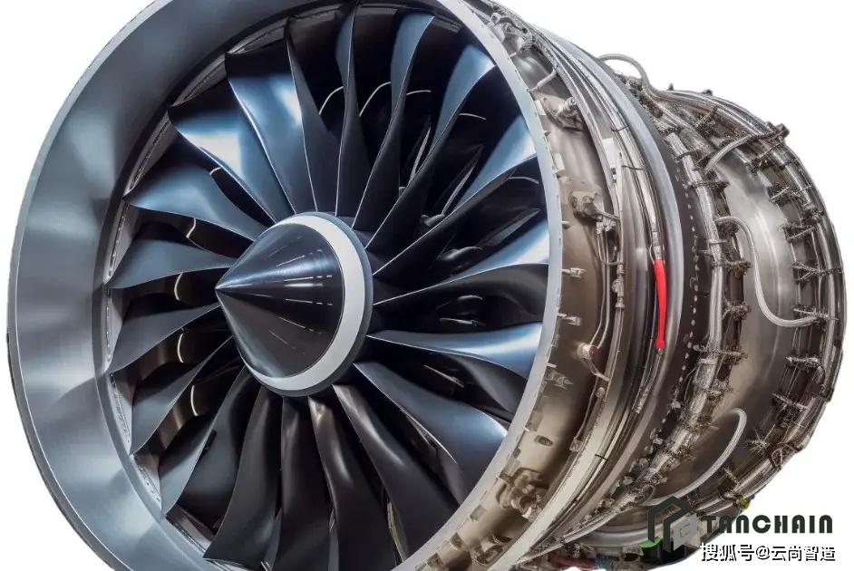
Nacelle cowls, fan case structures, and thrust reverser components have migrated to composites over successive engine generations. The drivers are mass, complex curvature that is easier to mould than to machine, and the ability to integrate stiffeners and attachment points into a single cured part rather than assembling dozens of metal details.
For higher-temperature zones, the composite is not the answer alone. Pre-oxidized fiber felt and fabric are used as thermal insulation and fire barriers around hot sections, and ceramic or glass systems take over where temperatures exceed what a polymer matrix can survive.
Spacecraft Bus, Satellites, and Launch Vehicle Structure
Spacecraft benefit from carbon fiber for reasons that overlap with aircraft but have their own emphasis: high specific stiffness for lightweight bus panels, near-zero thermal expansion for optical benches and antenna reflectors, and dimensional stability across the severe temperature swings of orbit. Satellite sandwich panels, launch vehicle interstages, fairing structures, and payload adapters are all established carbon fiber applications, and the thermal expansion argument is often the decisive one.
3. The Product Forms, One by One
Product form follows the manufacturing route. Choosing the form first and the process second is the most common way programmes lose time, so it is worth taking each form in turn and stating plainly what it is for.
3.1 Carbon Fiber Filament and Tow
Filament and tow are the base input. Aerospace-grade carbon fiber filament is supplied as continuous tow in standard counts, with controlled tensile strength and modulus, and it is used for filament winding of pressure vessels and drive shafts, for pultrusion, and as the fiber input to weaving and prepreg lines. Programs that place tight requirements on fiber uniformity start here, because tow quality propagates into every downstream product.
3.2 Carbon Fiber Fabric and Multiaxial NCF
Woven carbon fiber fabric — 3K plain or twill being the most widely recognised — provides balanced properties in two directions and a surface appearance that is often specified for exposed parts. Multiaxial NCF stacks unidirectional plies at defined orientations and stitches them together, which removes the crimp that woven fabric introduces and gives better in-plane properties per unit mass.
In aerospace, NCF is common for large infused structures where the ply orientations are defined by the stress analysis and the dry preform is laid up and infused in one operation.
3.3 Carbon Fiber Prepreg
Prepreg is fiber already impregnated with a precisely controlled quantity of resin, supplied as roll goods and stored under refrigeration. It is the dominant aerospace form for primary structure because fibre volume fraction, resin content, and volatile content are fixed before the part reaches the shop floor. Lay-up, debulk, and cure are then the only remaining variables, and each is documented in the process specification.
Prepreg suits autoclave cure, press cure and out-of-autoclave (OOA) routes. For aerospace work, the choice between them is a trade of capital cost against void content and mechanical performance, and it should be made deliberately rather than by default.
3.4 Carbon Fiber Plates and Laminates
Cured carbon fiber plates are flat laminates in the range from around 1 mm to 10 mm thick, produced in unidirectional or woven constructions. They serve brackets, ribs, mounting plates, and interface hardware, and they can be machined with carbide tooling into quite complex outlines. Because the laminate is cured under controlled pressure, a plate starts with a lower void content than a hand-laid part, which matters for fatigue-critical brackets.
Unidirectional plates give maximum stiffness along one axis and are the right choice when the load path is known and single-dominant. Woven plates spread stiffness across two axes and tolerate multi-directional loading and fastener holes better.
3.5 Pultruded and Roll-Wrapped Carbon Fiber Tubes and Profiles
Pultruded profiles pull continuous fiber through a heated die, producing constant-cross-section parts with very high fiber alignment along the axis and therefore very high axial stiffness and strength. In aerospace, pultruded profiles appear as stringers, floor beams, and stiffeners where a straight, highly aligned member is required.
Roll-wrapped and filament-wound tubes cover struts, tie rods, actuator linkages, and boom elements. Wall thickness and lay-up can be built up in steps, allowing local reinforcement at joints without adding mass along the whole length — useful for struts that see concentrated bearing loads at their ends.
4. The Measured Case: Why CFRP Wins in Aerospace
The advantages of carbon fiber in aerospace are measurable, and stating them with numbers is what makes a materials conversation productive rather than rhetorical.
4.1 Specific Strength and Specific Stiffness
Carbon fiber composites typically sit around 1.55–1.7 g/cm³, against roughly 2.7 g/cm³ for aluminum and 4.4 g/cm³ for titanium. Combined with the high tensile modulus of the fiber, this produces specific stiffness several times that of the metals, and that ratio — not absolute strength — is what governs a weight-driven aerospace design.
4.2 Fatigue Behaviour: Slow, Predictable, Inspectable
Metals fatigue by crack initiation and crack growth, and an aluminum structure can go from an acceptable crack to a critical one quickly. Carbon fiber laminates behave differently: damage tends to accumulate as matrix cracking and delamination spread gradually, and the resulting loss of stiffness is measurable. Structures can therefore be monitored and inspected against a predictable progression rather than an abrupt failure.
This does not mean composites are immune to fatigue. It means the failure mode is different, and a programme that designs and inspects for the right mode gets a longer, better-understood service life.
4.3 Thermal Expansion Matching for Precision Structures
Carbon fiber has a low coefficient of thermal expansion along the fiber direction, and by balancing ply orientations it is possible to design a laminate with near-zero or tailored expansion. For optical benches, antenna reflectors, and precision instrument mounts, this is often the reason carbon fiber is selected at all. A structure that does not change shape between a cold launch environment and an operating temperature keeps its alignment, and alignment is expensive to restore once the hardware is integrated.
4.4 Dimensional Stability and Moisture Effects
Aerospace laminates absorb a small amount of moisture from humid air, which causes slight swelling and a small reduction in glass transition temperature. Programmes handle this rather than ignore it: the laminate is designed for the conditioned state, and accelerated moisture conditioning is part of the qualification test sequence. The resulting dimensional changes are small and predictable, which is a very different proposition from an uncontrolled variable.
4.5 Corrosion and Galvanic Behaviour
Carbon fiber composites do not rust, and they resist the salt-laden environment that ground and maritime aerospace operations present. The one caution is galvanic: carbon is cathodic relative to aluminum and steel, so a direct metal-to-carbon joint in the presence of an electrolyte can drive corrosion of the metal. This is a solved problem — isolate the interface with a glass ply, a sealant, or a non-metallic fastener, and the joint is stable.
5. Selection Matrix: Requirement to Product Form
The table below maps the requirement a design team is most likely to be solving against the product form that addresses it. It is a starting point for specification, not a substitute for a structural analysis.
| Requirement / Sub-Assembly | Recommended Product Form | Typical Construction | Primary Reason |
|---|---|---|---|
| Wing skin and spar caps | Unidirectional prepreg | Autoclave-cured UD tape | Maximum axial stiffness per unit mass |
| Large fuselage panels | Multiaxial NCF | Resin infusion, stitched preform | No crimp, lower tooling cost for large area |
| Control surfaces | Prepreg skins with core | Sandwich, honeycomb or foam core | High torsional stiffness, low mass |
| Brackets, ribs, mounting plates | Carbon fiber plate | Machined UD or woven laminate | Fast, repeatable, easy to machine |
| Struts, tie rods, actuator linkages | Roll-wrapped or wound tube | Stepped wall, local end reinforcement | Axial stiffness with bearing-capable ends |
| Stringers and floor beams | Pultruded profile | High fibre alignment, constant section | Best axial properties at low unit cost |
| Optical benches, antenna reflectors | Quasi-isotropic prepreg laminate | Balanced ply schedule, near-zero CTE | Dimensional stability over temperature |
| Hot section insulation and fire barriers | Pre-oxidized fiber felt and fabric | Needled felt, woven cloth | Thermal insulation and flame resistance |
| Impact-prone fairings, interior panels | Aramid fabric, hybrid lay-up | Aramid/carbon hybrid laminate | Impact absorption, non-conductive surface |
6. Processing and Qualification Notes
Aerospace composites are decided as much in process control as in material selection. These are the points that most often determine whether a part meets its specification.
6.1 Lay-up Orientation Is the Design, Not a Detail
In an isotropic metal, properties are the same in every direction, so the drawing describes geometry only. In a laminate, the ply orientations are part of the design. Moving a ply from 45 degrees to 0 degrees changes the stiffness in a way no downstream process can compensate for. The ply schedule belongs in the released drawing and in the shop floor traveller, and any deviation should trigger a review rather than a workaround.
6.2 Curing Route Decides Your Void Content
Autoclave cure delivers the highest pressure and therefore the lowest void content, and it is the reference route for primary structure. Out-of-autoclave prepreg and resin infusion have improved substantially and are entirely appropriate for many secondary structures, but the void content is higher and the mechanical properties reflect it. Choose the route from the requirement, and document the consequence.
6.3 Machining, Drilling, and Fastener Practice
Carbon fiber machines well with carbide tooling at the right feeds and speeds, but it is abrasive and it delaminates if the tool pushes rather than shears. Drill with backing support, use a sharp drill and controlled feed, and avoid hand-held drilling on structural laminates. Bolted joints carry load through bearing and shear-out, so edge distances and hole quality matter more than they do in metal. Where possible, design the joint so that fiber runs continuously around the load rather than being cut through by a hole.
6.4 Galvanic Isolation and Lightning Strike Protection
Two electrical problems come with carbon fiber airframes, and both are managed rather than avoided. First, isolate carbon from aluminum and steel at every joint with a glass ply, sealant, or non-metallic fastener. Second, protect the structure from lightning strike: a metal mesh, conductive coating, or a dedicated conductive layer is bonded into the outer surface so the strike current has a defined path and the underlying laminate is not damaged by the arc.
6.5 Inspection and Traceability
Qualified aerospace composites are documented composites. Ultrasonic inspection detects voids and delamination. The material lot, cure cycle, and ply schedule travel with the part so that any later finding can be traced back. For a supplier, this means certificates of analysis and lot traceability are part of the product, not paperwork added afterwards. When specifying, ask for the lot data up front — it is a strong signal of whether a supplier is set up for aerospace work at all.
7. Supporting Fibers: Aramid and Pre-Oxidized in the Same Programme
Carbon fiber rarely carries an aerospace programme alone. Aramid filament and aramid fabric bring impact tolerance and electrical insulation, which makes them the natural partner in hybrid laminates for fairings, interior panels, and any surface where a conductive outer skin is undesirable. Pre-oxidized fiber yarn, fabric, and felt bring thermal insulation and flame resistance for hot-section barriers and fire walls, where a polymer matrix composite would not survive on its own.
Specifying these materials alongside the carbon fiber from a single supplier keeps the interfaces between them under control. A hybrid laminate is only as good as the compatibility of the plies within it, and compatibility is easier to guarantee when the material data comes from one place.
8. Why Tanchain for Aerospace Carbon Fiber Programs
Tanchain supplies the full carbon fiber chain that an aerospace programme needs: carbon fiber precursor, carbon fiber filament and tow, carbon fiber fabric, carbon fiber prepreg, machined carbon fiber plates, roll-wrapped and pultruded tubes and profiles, and finished carbon fiber parts. Alongside the carbon fiber, we supply aramid filament and aramid fabric for impact and insulation layers, and pre-oxidized fiber yarn, fabric, felt, and short fiber for thermal and flame barrier requirements.
That range matters in aerospace specifically because programmes rarely need one material. They need a documented, matched set — consistent specifications across primary structure, secondary structure, and the supporting insulation and impact layers, with lot traceability that survives an audit. Sourcing them together means the data package is coherent and the interfaces are understood.
If you are specifying carbon fiber for an airframe, a control surface, a spacecraft bus, or a nacelle structure, send us the requirement — load case, temperature range, mass target, and manufacturing route — and we will recommend the product forms, laminate constructions, and supporting materials that fit the programme. Explore our carbon fiber products and composite materials, or request a quote for your aerospace carbon fiber supply.