


-
Carbon Fiber Composite Hydrogen Storage Vessels: A Field Guide to Type IV Tanks
-
An engineering field guide to carbon fiber composite hydrogen storage vessels: Type III vs Type IV construction, polymer liners, filament winding and towpreg, qualification testing, material specification, and cost trends for 700 bar tanks.
Every kilogram a fuel cell truck saves on its storage system is a kilogram it can spend on payload. That single sentence explains why carbon fiber composite pressure vessels have moved from a niche engineering exercise to the center of the hydrogen economy. Steel cannot carry 700 bar efficiently, and plain aluminum is far too heavy for a mobile application, so the load-bearing job falls to a filament-wound carbon fiber shell. Hydrogen storage has become one of the most demanding and most valuable applications for carbon fiber composite materials anywhere in industry.
This field guide is written for engineers, vessel manufacturers, and procurement teams who are specifying carbon fiber composite pressure vessels or the carbon fiber inputs that go into them. It walks through vessel types, the tank architecture itself, the material forms that matter, the winding process, qualification testing, what to specify on a purchase order, and where the cost curve is heading.
How This Guide Is Organized
1 — Why Steel Goliahs Lost the Race
1.1 Gravimetric capacity decides the vehicle
1.2 The five vessel types
1.3 Where composite vessels are already deployed
2 — Inside a Type IV Vessel
2.1 The polymer liner
2.2 The carbon fiber overwrap
2.3 Boss, dome, and hoop sections
2.4 Why aramid hybrids appear in some designs
3 — Carbon Fiber Forms for Vessel Winding
3.1 Filament winding tow
3.2 Towpreg and dry fiber
3.3 Carbon fabric, chopped fiber, and pre-oxidized fiber
4 — Winding Technology and Design Practice
5 — Qualification Testing and Standards
6 — Specification Questions for Buyers
7 — Cost, Recycling, and What Comes Next
1. Why Steel Vessels Lost the Race for Carbon Fiber Composite Hydrogen Storage
Hydrogen storage was never a plumbing problem. It is a weight and pressure problem, and the numbers are unforgiving.
To store useful quantities of hydrogen in a reasonable volume, a vessel has to run at 350 bar or, for most on-board applications, 700 bar. A steel vessel capable of holding that pressure would weigh several times the gas it contains, which is tolerable for a stationary industrial cylinder and completely unworkable for a truck, a bus, or a forklift. The industry needed a material with very high specific strength, and carbon fiber composites were the only realistic answer.
1.1 Gravimetric Capacity Decides the Vehicle
Gravimetric capacity is the ratio of stored hydrogen mass to total system mass, and it drives vehicle range directly. Upgrading from a metal shell to a carbon fiber overwrap roughly halves the mass of the pressure boundary, which is the difference between a demonstration vehicle and a commercial one.
Hydrogen itself is light, so the vessel inevitably weighs far more than the gas it holds. The design goal is therefore to make the shell as thin and as efficient as the fiber and the safety factor allow, and to place every strand exactly where the stress demands it.
1.2 The Five Vessel Types
The industry classifies pressure vessels by construction, and the distinction matters when you specify materials.
| Type | Construction | Typical use |
|---|---|---|
| Type I | All-metal (steel) | Industrial gas, stationary storage |
| Type II | Metal liner with hoop-wound composite | Stationary and some transport |
| Type III | Aluminum liner with full carbon fiber overwrap | 350 bar and 700 bar mobile storage |
| Type IV | Polymer liner with full carbon fiber overwrap | 700 bar vehicle storage, buses, trucks, rail |
| Type V | Linerless composite shell | Weight-critical and emerging applications |
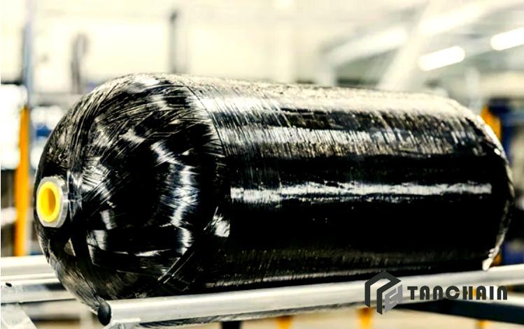
Type III vessels use an aluminum liner that shares part of the load, while Type IV vessels use a thin polymer liner that only acts as a permeation barrier, so the carbon fiber composite carries essentially the entire structural duty. That is why Type IV dominates new 700 bar vehicle programs: nothing is carried that does not have to be.
1.3 Where Composite Vessels Are Already Deployed
The installed base is broader than most people assume. Long-haul trucks and transit buses run Type IV tanks at 350 and 700 bar. Regional trains have entered commercial service on hydrogen. Materials handling fleets use composite cylinders in daily shift work. Backup power for data centers, refueling station buffer storage, marine vessels, and even aircraft demonstrators all rely on the same pressure vessel family.
The lesson for a materials buyer is that demand is no longer concentrated in one sector, so a supplier has to be able to serve several qualification regimes at once.
2. Inside a Type IV Carbon Fiber Hydrogen Storage Vessel
A Type IV vessel is a study in layered responsibilities. Every layer exists because something else cannot do that job well enough on its own.
2.1 The Polymer Liner Inside the Composite Hydrogen Storage Vessel
The liner is usually high-density polyethylene or a polyamide, and its primary job is to stop hydrogen from escaping through the composite. Because hydrogen molecules are the smallest in nature, permeation is a genuine design concern, and liner material selection and wall thickness are set by permeability targets rather than by mechanical load.
The liner is not designed to carry pressure. It sits on the inside, deforms with the tank, and has to stay bonded or at least remain compatible with the composite at temperature extremes. Liner to composite adhesion and the interlayer behavior between them are active areas of research, because debonding or liner wrinkling can compromise service life.
2.2 The Carbon Fiber Overwrap
The overwrap is the structure. Carbon fiber filament wound in a controlled pattern with an epoxy matrix absorbs the internal pressure load, and the vessel's burst rating, fatigue life, and weight all follow from how well that overwrap is designed.
Two fiber properties matter most here. Tensile strength determines how much pressure a given wall thickness can hold, and modulus determines how much the vessel grows under pressure, which in turn governs fatigue behavior over tens of thousands of pressure cycles. High-strength grades dominate pressure vessels today, and intermediate modulus grades appear where stiffness or cyclic performance is the binding constraint.
2.3 Boss, Dome, and Hoop Sections
A pressure vessel is not uniform. The cylindrical section is the easy part: hoop stress is twice the axial stress, so circumferential winding does most of the work and helical layers supply the axial component and hold the structure together.
The domes are where engineering effort concentrates. Fibers must turn from the cylinder onto the boss, and the dome thickness and the polar opening geometry determine whether the vessel fails at the cylinder or at the end cap. Design studies on grid theory optimization consistently show that dome winding layer thickness, ellipse ratio, and boss flange radius have a major influence on stress distribution and on whether the burst target is met with margin.
A note on boss design
Metal bosses are typically aluminum or stainless steel and carry the valve and the connection interface. Increasing the boss flange radius reduces liner stress under working pressure, but it also redistributes stress across the flange face in a way that leaves the center of the flange under-utilized. There is an optimum, and it is found through finite element analysis rather than by rule of thumb.
2.4 Why Aramid Hybrids Appear in Some Designs
Not every layer in a pressure vessel needs to be carbon. Aramid fiber offers very good impact and ballistic resistance at low density, so it is sometimes used as an outer protective layer over the carbon overwrap to absorb handling damage and fragment impact.
Hybridization also serves cost and supply strategy: the primary pressure-bearing layers stay carbon, while secondary and protective layers may use aramid fabric or a hybrid construction. Pre-oxidized fiber and its fabrics, which are inherently flame resistant and thermally stable, appear in fire protection and insulation layers around storage systems rather than in the pressure boundary itself.
3. Carbon Fiber Forms for Vessel Winding
What actually ships to a tank manufacturer is not "carbon fiber" in the abstract. It is a specific tow size, surface treatment, sizing chemistry, and package format, and each one affects the winding line.
3.1 Carbon Fiber Filament Winding Tow
Filament winding consumes continuous carbon fiber tow, most commonly in 12K and 24K formats, with larger tows used where deposition rate matters more than fine control. Tow size influences how quickly material can be laid down, how well the fiber wets out, and how tightly the band can follow the dome geometry.
Surface treatment and sizing are not cosmetic details. The sizing has to be compatible with the epoxy system and with the winding process, because poor compatibility shows up later as voids, dry spots, or reduced interlaminar shear strength. A supplier who controls sizing for the intended resin system saves the tank maker a great deal of trial and error.
3.2 Towpreg and Dry Fiber
There are two broad routes into the winding machine. In wet winding, dry carbon fiber tow passes through a resin bath on the way to the mandrel. In towpreg winding, the fiber arrives already impregnated with a precisely controlled resin content, and no bath is involved on the line.
Towpreg offers tighter control of resin content, a cleaner workshop, and better consistency from part to part, which is why it has gained ground in high-volume 700 bar tank production. Dry winding, where fiber is applied without matrix and later infused, is also under development for thermoplastic and linerless concepts. Each route asks for a different fiber format and a different sizing, and the choice should be made with the tank design, not after it.
3.3 Fabric, Chopped Fiber, and Other Inputs
Carbon fiber woven fabric and spread tow fabric are used for protective outer layers, for local reinforcement, and for test coupons and qualification panels. Chopped carbon fiber is used in molding compounds for valve bodies, brackets, and mounting hardware around the storage system where the load case does not justify continuous fiber.
Pre-oxidized fiber products, including filament, staple, yarn, and felt, are not pressure boundary materials, but they are genuinely useful in the surrounding system: thermal insulation around vessels, flame barriers, and fire protection in the enclosure. A hydrogen storage installation is a system, and the fiber list reflects that.
4. Winding Technology and Design Practice
The winding process translates a fiber specification into a structural part, and the process parameters are as important as the material.
4.1 Process Routes
Most 700 bar vessels are produced by wet winding or towpreg winding over a polymer liner that has been mounted on a mandrel. Helical layers pass around the domes and onto the boss; hoop layers run circumferentially over the cylinder. The sequence, angle, and thickness of each layer follow from the load case and the chosen safety factor.
Thermoplastic tape winding and automated fiber placement are the emerging alternatives. They offer faster cycle times and the possibility of weldable, recyclable structures, which aligns with where the industry says it wants to go. They also change the fiber format requirement, because tapes and towpregs are not interchangeable with dry tow on the same line.
4.2 What Drives the Design of a Carbon Fiber Storage Tank
The starting point is a target burst pressure with a defined safety margin above working pressure, plus a fatigue requirement expressed in pressure cycles. From there, design teams work through dome thickness, ellipse ratio, polar opening, boss flange geometry, and the split between helical and hoop layers.
Optimization studies of the dry towpreg winding process show that line tension, winding speed, and band width interact, and that a multi-objective approach is needed to balance void content, deposition rate, and mechanical performance. In practice, this means process development and material selection cannot be separated: a fiber that winds beautifully at one tension may behave differently in a different band configuration.
4.3 Quality Control on the Line
The measurable outcomes that matter are resin content, void content, fiber volume fraction, and the absence of gaps or overlaps in the band pattern. Modern lines track band placement, tension, and temperature, and log the results against each vessel's serial number.
For the buyer, the most useful question is not whether the manufacturer has a quality department, but whether individual vessels can be traced back to fiber lot, resin lot, and process record. In a 700 bar application, that traceability is the backbone of any recall decision.
5. Qualification Testing and Standards
Composite pressure vessels are regulated hardware. The test program is expensive and time consuming, and it shapes what materials are acceptable long before a purchase order is drafted.
5.1 The Core Test Sequence for a Carbon Fiber Pressure Vessel
A typical qualification program includes hydrostatic burst testing to demonstrate margin above working pressure, pressure cycling to validate fatigue life, leak-before-burst assessment, penetration and impact testing, and permeability measurement for the liner. Environmental conditioning adds extremes of temperature, humidity cycling, and in some cases exposure to hydrogen at pressure.
Burst pressure results in published design studies typically land in the range of 150 to 165 MPa for a 700 bar class cylinder, comfortably above the design value, which shows how much margin a well-optimized overwrap can provide.
5.2 Standards Landscape
Different regions rely on different frameworks, and manufacturers usually design to several at once. Stationary and transportable vessels, vehicle on-board storage, and refueling infrastructure each have relevant standards from organizations such as ISO, the US Department of Transportation, and European regulatory bodies, with United Nations packaging requirements applying to transportable cylinders.
The practical consequence for material suppliers is documentation. Test certificates, batch data, and material datasheets need to be available in the format that a notified body expects, because a gap in paperwork can delay a tank qualification by months.
6. Specification Questions for Buyers
What follows is a checklist for anyone procuring carbon fiber composite hydrogen storage vessels or the carbon fiber inputs to build them.
6.1 Vessel and System Questions
What working pressure and which safety factor does the design target, and to which standard?
Is the specification Type III or Type IV, and does the weight budget actually require Type IV?
What gravimetric capacity must be met at the system level, including valves and mounting?
How many pressure cycles must the vessel survive, and how is fatigue life demonstrated?
What liner material is used, and what permeation rate has been measured?
Can each vessel be traced to fiber lot, resin lot, and winding record?
6.2 Carbon Fiber Input Questions for Hydrogen Storage Tanks
Which tow size and surface treatment suit the winding line and the epoxy system?
Is the sizing specified for epoxy, and has compatibility been validated on the actual line?
Is the fiber supplied as dry tow, towpreg, or a mix across different layer types?
What are the batch-to-batch tolerances on tensile strength, modulus, and linear density?
Is hybrid aramid or protective fabric needed for the outer layers?
Are pre-oxidized fiber insulation and flame barrier materials required around the installation?
7. Cost, Recycling, and What Comes Next
The hydrogen storage industry has one dominant commercial problem, and it is not performance.
7.1 The Cost Structure of Carbon Fiber Hydrogen Storage
Carbon fiber is the largest single cost element in a Type IV vessel, often accounting for a substantial share of the total. That cost is driven by fiber price, by how efficiently fiber is converted into structural layers, and by labor and cycle time on the winding line. Reducing scrap, improving band placement accuracy, and moving toward towpreg and automated processes all attack the same problem from different directions.
Lower-cost grades, including larger tow counts and non-aerospace specification fiber, have made headway in stationary applications, but 700 bar mobile vessels remain conservative because the safety margins leave little room for material variability.
7.2 Recycling and End of Life
Recycled carbon fiber is becoming a practical input for secondary and non-critical parts, and the vessel industry is under growing pressure to plan for end-of-life composite recovery. Thermoplastic matrices are attractive precisely because they open a route to easier separation and reclamation.
7.3 Where the Technology Is Going
Three directions stand out. Linerless Type V vessels promise further weight reduction for weight-critical applications. Lower-cost, higher-accuracy winding systems keep pushing cycle time down. And the emergence of hydrogen in rail, marine, and aviation creates new pressure and geometry requirements that will pull the fiber market in new directions. Each of these trends increases rather than decreases the demand for well-specified, consistent carbon fiber.
The Takeaway
Carbon fiber composite pressure vessels sit at the intersection of the most demanding structural requirements and the fastest-growing energy market in the world. Getting the fiber format, the sizing, the winding process, and the documentation aligned is what separates a vessel that qualifies on the first attempt from one that stalls in testing. Buyers who define those inputs clearly, and suppliers who can trace them, both end up with a shorter and cheaper path to a qualified tank.
Tanchain supplies carbon fiber tow, carbon fiber filament, chopped carbon fiber, carbon fiber fabric, prepreg, aramid fiber and fabric, pre-oxidized fiber products, and hybrid constructions for pressure vessel and hydrogen storage programs. Explore our product range or contact our team to discuss the right carbon fiber specification for your next storage vessel project.