


-
Carbon Fiber Battery Enclosure Solutions: Cutting Weight, Adding Safety to EV and Energy Storage Packs
-
Carbon fiber prepreg, fabric, plates and pultruded profiles for battery pack enclosures - how CFRP lids, trays, crash structures and internal modules cut mass while meeting crash, thermal and insulation requirements in EV and grid storage packs.
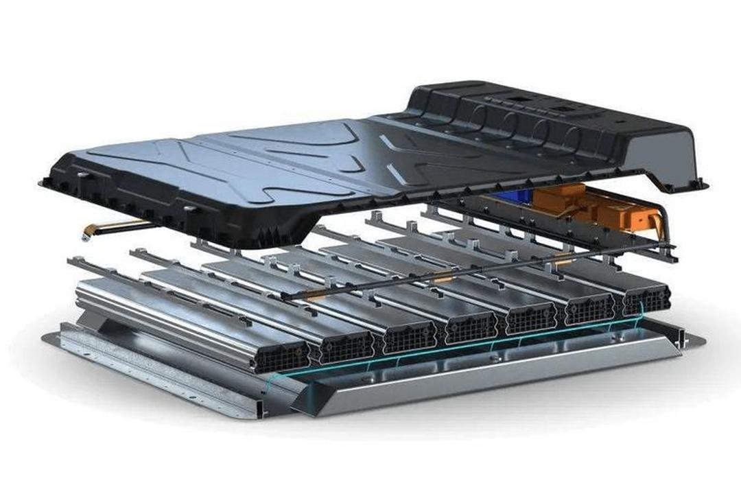
A battery pack is a strange thing to engineer. The cells inside it are sensitive to heat, crush, moisture, and vibration, yet the enclosure that protects them is expected to disappear from the vehicle or the rack as far as range, payload, and service access are concerned. That tension is exactly where carbon fiber earns its place. This solution guide walks through how carbon fiber composite enclosures and structural modules solve the real problems battery pack engineers face in electric vehicles, grid energy storage, and portable power systems — and how our carbon fiber prepreg, fabric, plates, and finished composite parts fit into each step.
What this guide covers
Why the enclosure is the hard part of a battery pack
The weight problem
The crash and intrusion problem
The thermal and electrical problem
How carbon fiber solves each of those problems
Strength-to-weight and stiffness-to-weight
Tailored anisotropy: stiffness where it matters
Thermal and electrical behaviour
Mapping the pack: which carbon fiber product goes where
Upper cover and lid
Lower tray, base plate, and crash structure
Internal modules, busbar carriers, and cell holders
Structural cross-members and battery box frames
Material forms and how to choose between them
Prepreg and autoclave or press cure
Fabric, NCF, and recycled short fiber
Pultruded profiles and machined plates
A selection matrix: requirement to product
| Requirement | Recommended carbon fiber form | Priority |
|---|---|---|
| Minimum lid mass, high stiffness | Thin quasi-isotropic prepreg laminate | Highest |
| Crash energy absorption at the sill | Woven fabric prepreg, braided tube | Highest |
| Flat base plate with sealing faces | Compression-moulded plate, machined CFRP sheet | High |
| Long stiff cross-members, low tooling cost | Pultruded carbon fiber profiles | High |
| Non-structural brackets and spacers | Recycled short-fiber compounds | Medium |
Implementation notes that decide whether the design works
Galvanic isolation
Fire and thermal runaway containment
Fastening, inserts, and sealing
Dielectric strength and insulation strategy
Supporting materials: aramid, pre-oxidized, and hybrid lay-ups
Why Tanchain for battery enclosure composites
1. Why the Enclosure Is the Hard Part of a Battery Pack
Cells get most of the attention, but the enclosure is where mass, safety, and manufacturing cost quietly accumulate. Getting it wrong shows up as lost range, failed crash tests, or a service nightmare. Three pressures pull against each other in every pack design.
1.1 The Weight Problem
A conventional steel or aluminium pack enclosure can add 20–35% to the mass of the cells it holds. In a passenger EV that extra mass is paid for twice — once as structure, and again as the larger battery needed to carry it. Where an enclosure is fitted high in the vehicle, it also raises the centre of gravity and hurts handling. Every kilogram removed from the enclosure is a kilogram available for cells, payload, or range.
1.2 The Crash and Intrusion Problem
The pack sits low and outboard, exactly where side impacts and underbody strikes concentrate load. The enclosure has to resist intrusion into the cell stack, absorb energy at the sill and the frame rails, and hold its shape so that cells are not pinched. Steel does this well but heavily. Aluminium does it more lightly but needs more section depth to reach the same stiffness.
1.3 The Thermal and Electrical Problem
A battery enclosure is also a thermal and electrical boundary. It must not short the pack, must manage heat paths, and in a thermal runaway event it is the last line of defence between a failing cell and the occupant or the surrounding rack. These requirements interact: a good thermal conductor is often a good electrical conductor, and both properties follow from the material choice.
2. How Carbon Fiber Solves Each of Those Problems
Carbon fiber reinforced polymer (CFRP) is not a single material but a design space. That is its advantage here: the laminate can be tuned to put stiffness, strength, and thermal behaviour where the load case demands, and to stay light everywhere else.
2.1 Strength-to-Weight and Stiffness-to-Weight
Carbon fiber composites deliver specific strength and specific stiffness several times higher than steel and markedly above aluminium. Translated into a pack, that means an enclosure of the same stiffness as an aluminium design can weigh 30–50% less, or the same mass can be spent on additional crash structure and still come out ahead. For grid storage racks, where dozens of enclosures stack in a container, the mass saved propagates through the whole support structure.
2.2 Tailored Anisotropy: Stiffness Where It Matters
Because the fibers carry load only along their length, the laminate can be laid up directionally. A lid can be thin and quasi-isotropic for handling and modal targets; a sill can be built with fibers running laterally to survive side intrusion; a floor can be biased for bending under the cell stack. This directional design is what lets a single material satisfy requirements that would otherwise need several different metals.
2.3 Thermal and Electrical Behaviour
Carbon fiber itself conducts heat and electricity, so a raw CFRP surface is not an insulator. That is a design consideration, not a defect: it can be used deliberately as a heat-spreading path, and then isolated electrically with glass or aramid surface plies, coatings, or dedicated insulation layers. Chapter 5 covers this in practice.
3. Mapping the Pack: Which Carbon Fiber Product Goes Where
A pack is not one part, and the right carbon fiber form differs section by section. The most reliable approach is to map the enclosure structurally before choosing materials.
3.1 Upper Cover and Lid
What the lid has to do
The lid carries no cell load but must stay flat, seal against the tray, and survive repeated opening during service. It is also the panel most exposed to handling damage during assembly, so surface durability matters as much as stiffness.
The typical lay-up
The lid is usually the largest single panel and the easiest place to save mass. A thin carbon fiber prepreg laminate — two to four plies in a quasi-isotropic stack — gives a stiff, flat cover that holds its shape through thermal cycling and meets sealing-face flatness targets. Compression-moulded or autoclave-cured lids also accept moulded ribs and inserts, so stiffness comes from geometry rather than extra thickness.
3.2 Lower Tray, Base Plate, and Crash Structure
Load path first
Before choosing a material, trace where an underbody strike or a side impact sends load. If the path runs through the tray, the tray is structural; if it bypasses into frame rails, the tray can be optimised for sealing and stiffness alone.
Tray versus base plate
The lower tray carries the cells and takes the underbody load case. Here the requirement is not just stiffness but energy absorption. Woven carbon fiber fabric prepreg and braided tubes crush progressively and predictably, which is why they appear in sill inserts and crash cans around the pack. A flat, sealed base plate is typically a compression-moulded or machined CFRP sheet, chosen for flatness and machinability.
3.3 Internal Modules, Busbar Carriers, and Cell Holders
Inside the enclosure, mass still matters but so do space and part count. Thin carbon fiber plates and machined composite brackets can act as module frames, busbar carriers, and cell holders, replacing a set of metal parts with fewer, lighter components. Because these parts are often non-structural, recycled short fiber formulations become viable and cost-effective here.
3.4 Structural Cross-Members and Battery Box Frames
Long straight members — cross-members, rails, and battery box frames — are where pultruded carbon fiber profiles shine. Pultrusion produces constant-section profiles with continuous fiber along the axis, giving high axial stiffness at low tooling cost, which is ideal for a member that simply needs to be stiff, straight, and light.
4. Material Forms and How to Choose Between Them
4.1 Prepreg and Autoclave or Press Cure
Carbon fiber prepreg gives the highest fibre volume fraction and the most consistent mechanical properties, which matters for crash and structural parts where you need predictable, documentable performance. It carries the higher processing cost, so it is usually reserved for the lid, the crash structure, and primary load paths.
4.2 Fabric, NCF, and Recycled Short Fiber
Woven carbon fiber fabric and non-crimp fabric are the workhorses for moulded panels with compound curvature. They drape well, tolerate a range of processes, and give good out-of-plane properties in the crash zones. Where the part is non-structural, recycled short fiber compounds reduce cost and support sustainability targets.
4.3 Pultruded Profiles and Machined Plates
Pultruded profiles and machined carbon fiber plates serve the linear and flat elements. They need little or no tooling, can be cut, drilled, and bonded in-house, and convert a complex enclosure into a kit of well-understood parts. This is often the fastest route from design to a working prototype pack.
5. A Selection Matrix: Requirement to Product
The table below is the shortcut we use with pack engineers when a design is still fluid. Read it left to right: the requirement drives the material form, which then drives the procurement question.
| Requirement | Recommended carbon fiber form | Priority |
|---|---|---|
| Minimum lid mass, high stiffness | Thin quasi-isotropic prepreg laminate | Highest |
| Crash energy absorption at the sill | Woven fabric prepreg, braided tube | Highest |
| Flat base plate with sealing faces | Compression-moulded plate, machined CFRP sheet | High |
| Long stiff cross-members, low tooling cost | Pultruded carbon fiber profiles | High |
| Non-structural brackets and spacers | Recycled short-fiber compounds | Medium |
6. Implementation Notes That Decide Whether the Design Works
Material choice is only half the story. Four details decide whether a carbon fiber enclosure performs in the field or fails in validation.
6.1 Galvanic Isolation
Where it bites
Corrosion appears first at bolt holes, rivet lines, and any bracket that touches raw CFRP while staying wet. Brackets are the usual first failure point in field service.
Design fix
Carbon fiber is cathodic relative to aluminium and steel. Where a CFRP part meets a metal fastener or bracket, the metal corrodes. The standard fix is a glass or aramid insulating ply at the interface, isolating washers or bushings, and a sealant that keeps moisture out of the joint. This is cheap to design in and expensive to retrofit.
6.2 Fire and Thermal Runaway Containment
An enclosure is expected to give occupants and surrounding equipment time to escape a thermal runaway. Carbon fiber composites can be combined with intumescent coatings, aramid felts, or pre-oxidized fiber barriers to form a layered passive protection system that delays flame and heat transfer. The barrier is designed as a system, not as a single material.
6.3 Fastening, Inserts, and Sealing
Composites do not like point-loaded bolts. The reliable approach is moulded-in or bonded inserts, spread load paths, and sealing faces designed with enough flatness to take a gasket. Bolted joints through a laminate should always be designed with adequate edge distance and bearing area, and where possible replaced with bonded or hybrid joints.
6.4 Dielectric Strength and Insulation Strategy
Because carbon fiber conducts, the electrical insulation of the pack cannot rely on the structural composite. Design in dedicated insulation — glass surface plies, insulating films, or coatings — and treat the CFRP structure as a conductive body that must be electrically isolated and grounded as intended.
7. Supporting Materials: Aramid, Pre-Oxidized, and Hybrid Lay-Ups
Carbon fiber rarely works alone in a battery enclosure. Aramid long fiber and aramid fabrics add impact tolerance and electrical insulation, which makes them a natural partner for carbon fiber in hybrid laminates. Pre-oxidized fiber yarn, fabric, and felt bring flame resistance and thermal insulation into the lay-up, useful around the runaway barrier and around hot components. Glass fiber remains the standard isolating ply at metal interfaces. Together these materials let the enclosure meet mechanical, thermal, and electrical requirements in one structure rather than three separate ones.
8. Why Tanchain for Battery Enclosure Composites
Tanchain supplies the full carbon fiber chain that a battery enclosure programme needs: carbon fiber precursor, carbon fiber filament, carbon fiber fabric, carbon fiber prepreg, machined carbon fiber plates, pultruded profiles, and finished carbon fiber parts, alongside aramid filament, aramid fabric, and pre-oxidized fiber yarn, fabric, and felt for the insulating and flame-barrier layers. That range means a pack team can source a matched, documented material set for the lid, tray, crash structure, internal modules, and barriers from a single supplier, with consistent specifications across the whole enclosure.
If you are designing or re-specifying a battery enclosure for an EV, grid storage container, or portable power system, send us the requirements — mass target, crash case, thermal case, and enclosure architecture — and we will recommend the material forms and lay-ups that fit. Explore our carbon fiber products and composite solutions, or request a quote for your program.